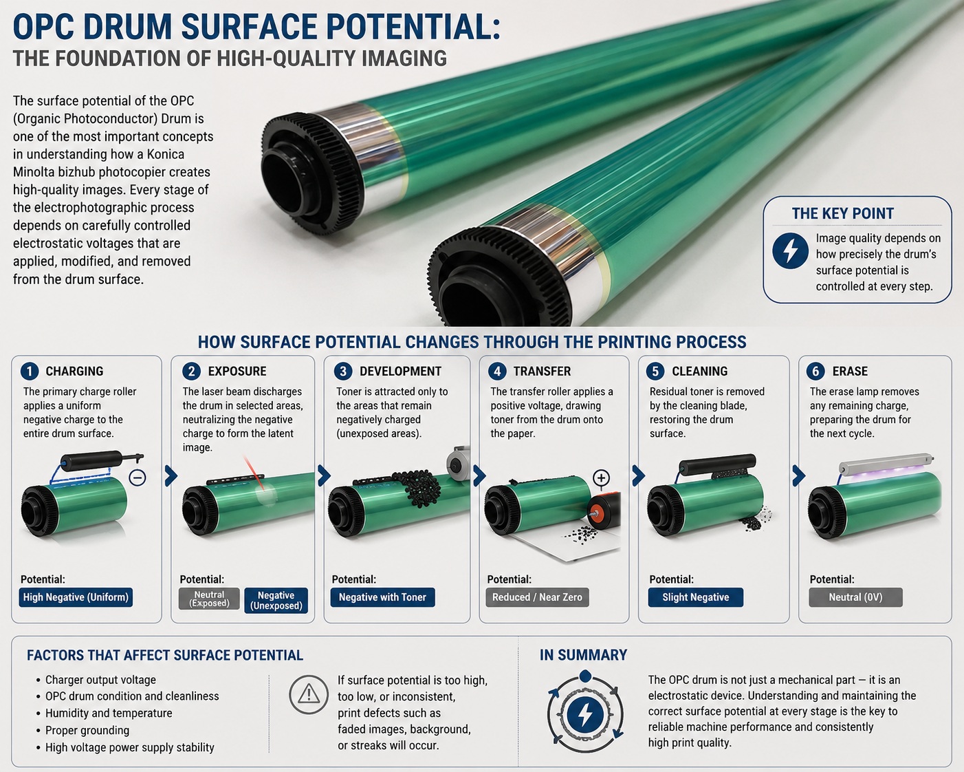
The surface potential of the OPC (Organic Photoconductor) Drum is one of the most important concepts in understanding how a Konica Minolta bizhub photocopier creates high-quality images. Every stage of the electrophotographic process depends on carefully controlled electrostatic voltages that are applied, modified, and removed from the drum surface.
The drum does not simply attract toner because it is “charged.” Instead, the machine creates a series of controlled electrical potential differences between the:
- OPC Drum
- Primary Charge Roller
- Laser Scanner Unit (LSU)
- Developer Roller
- Transfer Roller or Intermediate Transfer Belt (ITB)
- Drum Discharge System
These voltage differences determine exactly where toner is deposited, transferred, and removed.
A properly controlled surface potential provides:
- Sharp image edges
- Stable image density
- Accurate grayscale reproduction
- Clean backgrounds
- Consistent color registration
- Reliable toner transfer
When surface potentials become unstable, technicians may observe:
- Light prints
- Gray backgrounds
- Toner scattering
- Density fluctuations
- Poor transfer efficiency
- Ghost images
- Developer-related error codes
Understanding surface potential is essential for diagnosing print quality problems and high-voltage system faults.
What Is Surface Potential?
Surface potential is the electrical voltage present on the surface of the OPC drum at any point during the imaging process.
It is measured relative to electrical ground and is typically expressed in volts (V).
The voltage on the drum changes continuously as it moves through each stage of the print cycle.
Why Surface Potential Matters
Toner particles respond to differences in electrical potential, not to absolute voltage.
The imaging system controls toner movement by carefully creating voltage differences between:
- The drum
- The developer roller
- The transfer system
Without these voltage differences:
- Toner would not know where to move.
- Images could not be formed.
- Printing would be impossible.
The Surface Potential Throughout the Imaging Cycle
The drum passes through several distinct electrical states during one complete rotation.
Stage 1: Before Charging
Before reaching the Primary Charge Roller:
The drum has been:
- Cleaned
- Discharged
Surface potential is approximately:
0 V
At this point:
- No latent image exists.
- No toner is present.
- The drum is electrically neutral.
Stage 2: Primary Charging
The Primary Charge Roller applies a uniform electrostatic charge across the drum.
Typical surface potential:
Approximately -500 V to -800 V
(The exact value depends on the bizhub model and environmental conditions.)
The entire drum surface now has:
- Uniform electrical potential
- Stable charge
- No visible image
Every location on the drum begins at nearly the same voltage.
Stage 3: Laser Exposure
The Laser Scanner Unit selectively exposes portions of the drum.
Where the laser strikes:
- The OPC coating becomes conductive.
- Surface charge dissipates.
- Voltage decreases.
Typical exposed potential:
Approximately -50 V to -150 V
Unexposed areas remain near their original charging voltage.
This creates the invisible electrostatic latent image.
The Electrostatic Latent Image
After laser exposure:
| Area | Typical Surface Potential |
|---|---|
| Unexposed area | -600 V |
| Laser-exposed area | -100 V |
Only the electrical potential has changed.
Nothing is yet visible.
The drum now contains a pattern of different voltages that represents the page image.
Stage 4: Development
The Developer Roller presents charged toner to the drum.
The developer bias voltage is carefully selected so that toner moves only to the desired image areas.
Example:
| Component | Example Voltage |
|---|---|
| Drum background | -600 V |
| Image area | -100 V |
| Developer bias | -350 V |
Because of the electrical potential differences:
- Toner is attracted to the image areas.
- Background areas reject toner.
This creates the visible toner image.
Stage 5: Image Transfer
The transfer roller or Intermediate Transfer Belt applies an opposite electrical charge.
This produces a stronger electrical attraction than the drum can provide.
As a result:
- Toner leaves the drum.
- Toner transfers to the paper or ITB.
The drum loses nearly all of its toner image.
Stage 6: Drum Cleaning
A small amount of toner remains.
The Cleaning Blade removes:
- Residual toner
- Toner contamination
Only a clean drum surface continues.
Stage 7: Drum Discharge
Even after cleaning, small electrical charges remain.
The erase lamp or drum discharge system neutralizes these remaining charges.
Surface potential returns to approximately:
0 V
The drum is now ready for the next print cycle.
Surface Potential Throughout One Complete Rotation
| Process Stage | Approximate Drum Surface Potential* |
|---|---|
| Drum discharged | 0 V |
| Primary charging | -500 to -800 V |
| Laser-exposed image area | -50 to -150 V |
| Unexposed background | -500 to -800 V |
| After toner development | Voltage differences remain beneath the toner image |
| After transfer | Most toner removed; residual charge remains |
| After discharge | Approximately 0 V |
*These values are representative ranges used to explain the imaging process. Actual operating voltages vary by Konica Minolta bizhub model, engine design, firmware, environmental conditions, and service adjustments. Always refer to the official service manual for model-specific specifications.
Why Voltage Differences Matter More Than Absolute Voltage
The developer system responds to voltage differences rather than a single fixed voltage.
Example:
| Component | Voltage |
|---|---|
| Developer Roller | -350 V |
| Background | -600 V |
| Image Area | -100 V |
The voltage difference determines where toner is attracted.
This principle allows the machine to produce:
- Sharp text
- Smooth gradients
- High-resolution graphics
Factors That Affect Surface Potential
Several factors influence the drum’s electrical characteristics.
OPC Drum Condition
A worn photoconductive coating may:
- Hold less charge
- Discharge unevenly
- Produce unstable image density
Primary Charge Roller
Contamination or wear can cause:
- Uneven charging
- Background shading
- Density variations
Laser Scanner Unit
Weak or blocked laser exposure may leave too much charge on intended image areas, resulting in:
- Light prints
- Missing image detail
- Weak halftones
Developer Bias Voltage
Incorrect bias voltage can produce:
- Gray background
- Light prints
- Toner scattering
- Poor image contrast
Environmental Conditions
High humidity may:
- Increase charge leakage
- Reduce electrostatic efficiency
Low humidity may:
- Increase static electricity
- Affect toner charging
Modern bizhub machines compensate automatically for many environmental changes through Image Stabilization and ATDC control.
Common Print Defects Caused by Incorrect Surface Potential
| Print Symptom | Possible Cause |
|---|---|
| Light prints | Low drum charge, weak laser exposure, incorrect developer bias |
| Gray background | Poor charge retention or incorrect bias voltage |
| Uneven density | Non-uniform charging or worn OPC drum |
| Ghost images | Incomplete drum discharge or poor cleaning |
| Toner scattering | Incorrect toner charging or unstable surface potential |
| Weak halftones | Inconsistent laser discharge or developer bias |
Diagnostic Procedure for Technicians
Step 1: Print Internal Test Pages
Evaluate:
- Solid fills
- Halftones
- Gradation charts
- Background cleanliness
Step 2: Inspect the Charging System
Check:
- Primary Charge Roller
- High-voltage contacts
- Drum grounding
- Electrical connectors
Step 3: Inspect the OPC Drum
Look for:
- Surface wear
- Scratches
- Toner contamination
- Coating damage
Step 4: Verify the Developer System
Inspect:
- Developer condition
- ATDC (TCR) values
- Developer sleeve
- Toner concentration
Incorrect developer operation often changes the apparent surface potential behavior.
Step 5: Check High-Voltage Outputs
If specified by the service manual:
Verify:
- Primary charging voltage
- Developer bias voltage
- Transfer voltage
Only use approved service procedures and measuring equipment when testing high-voltage circuits.
Common Technician Mistakes
Assuming Light Prints Always Mean a Bad Drum
Light images may also result from:
- Incorrect developer bias
- Toner supply problems
- Laser Scanner Unit contamination
- High-voltage power supply faults
Always evaluate the complete imaging system.
Ignoring Environmental Effects
Humidity and temperature can influence electrostatic behavior.
If image quality changes with environmental conditions, perform the recommended stabilization and calibration procedures before replacing components.
Replacing Components Without Reviewing High-Voltage Conditions
A faulty high-voltage power supply can produce symptoms similar to worn drums or developer units.
Verify electrical operation before replacing expensive imaging components.
Preventive Maintenance
To maintain stable surface potential:
- Use genuine Konica Minolta toner.
- Keep the Primary Charge Roller clean.
- Avoid touching the OPC drum surface.
- Perform scheduled Image Stabilization procedures.
- Replace the OPC drum and developer at the recommended maintenance intervals.
- Follow all high-voltage adjustment procedures in the service manual.
Relationship Between Surface Potential and the Electrophotographic Process
| Process Stage | Surface Potential Function |
|---|---|
| Primary Charging | Creates a uniform electrostatic field |
| Laser Exposure | Selectively lowers the drum’s potential to form the latent image |
| Development | Voltage differences guide toner onto the image areas |
| Transfer | Opposite charge moves toner from the drum to the ITB or paper |
| Cleaning | Removes remaining toner without changing the image-forming process |
| Discharge | Returns the drum to an electrically neutral state for the next cycle |
Why Understanding Surface Potential Matters
Surface potential is the invisible foundation of the entire electrophotographic process. Every stage of image formation—from charging and laser exposure to toner development and transfer—depends on carefully controlled electrostatic voltages. Even small changes in these voltages can significantly affect image density, background cleanliness, and overall print quality.
By understanding how surface potential changes throughout the drum’s rotation and how each imaging component contributes to those changes, Konica Minolta service technicians can accurately diagnose print defects, distinguish between drum, developer, charging, and transfer problems, and perform more efficient, reliable repairs.
Conclusion
The surface potential of the OPC drum is the electrical blueprint that guides every stage of image formation in a Konica Minolta bizhub machine. Beginning with a uniform charge applied by the Primary Charge Roller, selectively reduced by the Laser Scanner Unit, modified during toner development, and finally neutralized after cleaning, the drum’s continuously changing electrostatic voltage makes precise toner control possible.
Working together with the high-voltage power supply, Developer Unit, Transfer System, and Drum Cleaning System, these controlled voltage differences enable sharp text, smooth halftones, accurate color reproduction, and consistent image quality. A thorough understanding of surface potential allows Konica Minolta technicians to diagnose electrostatic imaging problems confidently and maintain the high performance expected from bizhub multifunction systems.