Paper path sensors are among the most important components inside every Konica Minolta bizhub multifunction printer. Although they are small and inexpensive, these sensors are responsible for monitoring every sheet of paper as it travels from the paper tray to the output tray. The machine relies on them to detect paper movement, synchronize image formation, prevent collisions between sheets, and quickly identify the exact location of paper jams.
Most Konica Minolta bizhub models use photo-interrupter sensors, also called optical paper sensors, which consist of an infrared (IR) emitter, an infrared receiver, and a movable plastic actuator (commonly called a sensor flag). As paper moves through the machine, it changes the position of the actuator, allowing the controller board to determine whether paper is present.
Understanding how these sensors work is essential for every field technician because a large percentage of paper jams, intermittent feed problems, and false jam errors are caused by dirty sensors, damaged actuator flags, or incorrect sensor timing rather than failed electronic boards.
What Is a Photo-Interrupter Sensor?
A photo-interrupter is a non-contact optical sensor that detects the presence or absence of an object by interrupting an infrared light beam.
Unlike mechanical switches, photo-interrupters have no electrical contacts that wear out during normal operation.
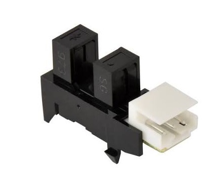
A typical paper sensor consists of:
- Infrared LED (Emitter)
- Infrared Phototransistor (Receiver)
- Plastic housing
- U-shaped sensing slot
- Plastic actuator flag
- Return spring (on some models)
- Electrical connector
The emitter and receiver are permanently aligned inside the sensor body.
Basic Operating Principle
Without paper inside the sensor area, the actuator flag remains in its normal position.
The infrared light reaches the receiver.
No Paper

IR LED  ------------->  Receiver

Light Path = Clear

Controller Input = ON
When paper enters the sensor area, it pushes the actuator flag.
The flag blocks the infrared beam.
Paper Arrives

IR LED ---> |FLAG| ---> Receiver

Light Blocked

Controller Input = OFF
The controller immediately detects the signal transition.
Instead of detecting paper directly, the sensor actually detects the movement of the actuator flag.
Why Infrared Light Is Used
Infrared light offers several advantages:
- Invisible to users
- Immune to most ambient lighting
- Low power consumption
- Long service life
- High switching speed
- Excellent reliability
- No mechanical electrical contacts
Infrared LEDs typically operate for tens of thousands of hours under normal conditions.
Sensor Components
Infrared LED (Emitter)
The emitter continuously produces infrared light whenever the machine is powered.
Characteristics include:
- Narrow light beam
- Low heat generation
- Long operational life
- Stable output
The controller supplies regulated voltage to the LED.
Phototransistor (Receiver)
The receiver detects incoming infrared light.
When illuminated:
- Current flows
- Signal changes state
When blocked:
- Current stops
- Logic level changes
The controller monitors this signal continuously.
Actuator Flag
The actuator flag is the only moving part.

It is usually made from black plastic to completely block infrared light.
Functions include:
- Detect paper edge
- Detect paper exit
- Trigger timing events
- Prevent false detection
Why the Flag Is Black
Black plastic absorbs infrared light very effectively.
This provides:
- Accurate switching
- High contrast
- Reliable operation
- Minimal light leakage
Transparent plastics would allow partial infrared transmission and unreliable detection.
Sensor Locations Throughout the Paper Path
A typical Konica Minolta bizhub machine contains many paper path sensors.
Common locations include:
Paper Feed Section
- Tray paper feed sensor
- Pickup sensor
- Feed sensor
Purpose:
Detect successful sheet pickup.
Registration Section
Registration sensor
Purpose:
Synchronize paper with the latent image on the drum.
Transfer Section
Transfer entrance sensor
Purpose:
Confirm paper reaches the transfer belt correctly.
Fusing Section
Fuser entrance sensor
Fuser exit sensor
Purpose:
Monitor paper entering and leaving the fuser assembly.
Exit Section
Exit sensor
Purpose:
Confirm successful paper delivery.
Duplex Unit
Duplex entrance sensor
Duplex reverse sensor
Duplex exit sensor
Purpose:
Track sheets during two-sided printing.
Automatic Document Feeder (ADF)
ADF feed sensor
ADF registration sensor
ADF exit sensor
Purpose:
Monitor original document movement.
Finisher
Entrance sensor
Transport sensor
Stack sensor
Exit sensor
Purpose:
Coordinate stapling, punching, folding, and paper delivery.
Paper Tracking Through the Machine
A single sheet activates multiple sensors in sequence.
Tray

↓

Pickup Sensor

↓

Registration Sensor

↓

Transfer Sensor

↓

Fuser Entrance

↓

Fuser Exit

↓

Exit Sensor

↓

Output Tray
Each transition is expected to occur within a specific time window programmed into the firmware.
How the Controller Uses Sensor Timing
The controller does not simply determine whether paper is present.
It also measures:
- Arrival time
- Departure time
- Delay between sensors
- Sensor activation duration
- Paper speed
- Paper length estimation
- Transport synchronization
For example:
Pickup Sensor ON

↓

0.32 sec

↓

Registration Sensor ON

↓

0.54 sec

↓

Transfer Sensor ON

↓

0.47 sec

↓

Exit Sensor ON
If one transition occurs too early, too late, or not at all, the firmware interprets this as a transport fault and stops the machine to prevent damage.
Registration Timing
The registration sensor is one of the most critical paper sensors.
Its functions include:
- Detect leading edge
- Align paper
- Synchronize drum image
- Correct image placement
The controller uses the registration sensor signal to determine the exact moment the registration rollers release the sheet.
This synchronization ensures that the toner image on the drum transfers to the correct location on the paper.
Jam Detection Logic
Paper jam detection is based almost entirely on sensor timing.
Example:
Expected sequence:
Pickup

↓

Registration

↓

Transfer

↓

Fuser

↓

Exit
Possible faults include:
- Paper never reaches registration sensor
- Paper stops before fuser
- Paper remains at exit sensor
- Two sensors activated simultaneously
- Sensor never resets
Each condition generates a specific jam location to assist troubleshooting.
Types of Paper Jam Detection
Arrival Timeout
Paper does not arrive within the expected time.
Possible causes:
- Pickup roller wear
- Empty tray
- Feed clutch failure
- Separation failure
Exit Timeout
Paper enters but never exits.
Possible causes:
- Fuser jam
- Torn paper
- Exit roller failure
Sensor Stuck ON
The actuator flag remains blocked.
Possible causes:
- Broken flag
- Obstruction
- Paper fragment
- Failed sensor
Sensor Stuck OFF
The sensor never detects paper.
Possible causes:
- Broken actuator
- Misaligned flag
- Faulty emitter
- Open wiring
Common Sensor Failure Modes
Dirty Optical Window
Paper dust and toner accumulate on the sensor.
Symptoms:
- Random jams
- Intermittent detection
- False paper errors
Repair:
Clean the sensor opening with compressed air or a lint-free swab lightly moistened with isopropyl alcohol.
Broken Actuator Flag
Plastic flags may crack or break.
Symptoms:
- Permanent jam indication
- Paper not detected
- Inconsistent operation
Repair:
Replace the actuator.
Weak Return Spring
Some actuator assemblies use small springs.
Symptoms:
- Flag does not return
- Delayed detection
- Random jams
Repair:
Replace the actuator assembly or spring if available.
Bent Actuator
Improper jam removal may bend the flag.
Symptoms:
- Incorrect switching point
- Timing errors
- Registration faults
Repair:
Replace the damaged actuator rather than attempting to reshape it.
Failed Infrared LED
A failed emitter produces no infrared light.
Symptoms:
- Constant sensor state
- Immediate paper jam
- Service mode input never changes
Repair:
Replace the sensor assembly.
Failed Phototransistor
The receiver cannot detect infrared light.
Symptoms:
- Constant ON
- Constant OFF
- Unstable switching
Repair:
Replace the sensor assembly.
Wiring Harness Problems
Connector issues may interrupt sensor signals.
Possible causes:
- Loose connector
- Broken wire
- Pin corrosion
- Harness damage
Always inspect wiring before replacing electronic components.
Diagnosing Paper Path Sensors
Visual Inspection
Check for:
- Paper scraps
- Toner buildup
- Dust accumulation
- Damaged actuator
- Loose connectors
- Broken mounting tabs
Manual Actuation Test
Move the actuator by hand.
It should:
- Move smoothly
- Return freely
- Not stick
- Produce a clear state change in Service Mode
Service Mode I/O Check
Most Konica Minolta bizhub models provide an Input/Output Check or Sensor Check screen.
Procedure:
- Enter Service Mode.
- Open the sensor or I/O monitoring menu.
- Locate the paper path sensor input.
- Move the actuator manually.
- Verify that the displayed status changes immediately between ON and OFF.
- If the input does not change, inspect the actuator, clean the sensor, check the connector and wiring, then replace the sensor only after these checks are completed.
Continuity Testing
Disconnect power before measuring resistance.
Verify:
- Harness continuity
- Connector integrity
- Supply voltage (according to the service manual)
- Proper grounding
Preventive Maintenance
During scheduled maintenance:
- Remove paper dust from all optical sensors.
- Clean actuator slots carefully.
- Verify free movement of every sensor flag.
- Check for cracked or worn actuator levers.
- Inspect harness routing after servicing the paper path.
- Confirm proper sensor operation using Service Mode before returning the machine to the customer.
Regular cleaning significantly reduces intermittent paper jams and unnecessary service calls.
Best Practices for Field Technicians
- Never lubricate optical sensors or actuator flags, as lubricants attract dust and interfere with movement.
- Remove all paper fragments after a jam; even a small piece lodged behind a flag can cause repeated false jam errors.
- Replace broken actuator flags rather than attempting to glue or repair them, as even slight misalignment affects timing.
- When replacing paper transport assemblies, verify that every actuator flag is correctly positioned in its sensor slot.
- Use the machine’s jam history together with real-time sensor status to identify the first sensor that failed to change state instead of replacing multiple parts unnecessarily.
- Compare actual sensor timing with the specifications in the service manual for the exact bizhub model being serviced.
Preventive Maintenance Checklist
| Inspection Item | Recommended Action |
|---|---|
| Optical sensor openings | Remove paper dust and toner contamination |
| Infrared emitter/receiver area | Clean carefully with a lint-free swab if needed |
| Actuator flags | Check for cracks, wear, and free movement |
| Return springs | Verify proper return action where applicable |
| Sensor mounting | Ensure the sensor is securely installed and aligned |
| Wiring harnesses | Inspect connectors, pins, and cable routing |
| Service Mode sensor test | Confirm each paper path sensor switches correctly |
| Jam history | Review recurring jam locations before replacing parts |
Conclusion
Photo-interrupter paper path sensors are the primary “eyes” of a Konica Minolta bizhub printer. By combining an infrared emitter, a receiver, and a simple mechanical actuator flag, they provide precise, non-contact detection of paper movement throughout the machine. The controller uses not only the ON/OFF state of these sensors but also their exact timing to synchronize image formation, monitor paper transport, and identify the location of jams.
For field technicians, a thorough understanding of paper path sensors is fundamental to efficient troubleshooting. Careful inspection, cleaning, actuator verification, Service Mode testing, and analysis of sensor timing often resolve paper feed problems without replacing expensive assemblies, resulting in faster repairs, improved reliability, and reduced service costs.